More Colors, More Visuals, Some Math
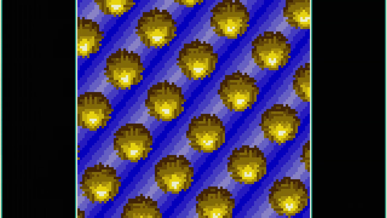
The latest addition to my homebrew 6502 computer is more colorful graphics output. To be specific, the system now supports output in 256 colors. As a little exercise, I’ve implemented a rotozoom effect to put the system through its paces. In this post, I’ll cover the hardware, the effect, and the implementation. Before getting into the details, you can find a YouTube video below showing the system in action. You can view the effect about one minute into the video.
The Hardware
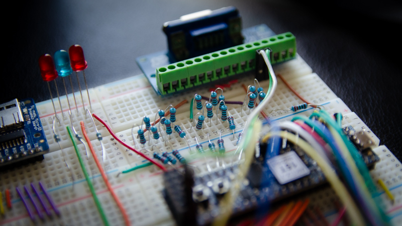
Since the last iteration, not a whole lot changed with the hardware. The 3 resistors (one each for the output of the red, green, and blue color channels) have been replaced with R-2R ladders, similar to the ones in the VGA From Scratch and Arduino Raster Bars projects. Either of those projects ran at 5V while the 6502 computer runs at 3.3V. I opted for 220Ω for R to accommodate. For the 2R parts, I use two 220Ω resistors in series (since I happened to have a bunch of those in my toolbox).
The changes to the FPGA are also minimal. There’s no palette or indexed color scheme implemented, and each byte is interpreted directly as BBGGGRRR data, i.e. 3 bits red, 3 bits green, and 2 bits blue color information. Since the video module already fetches a whole byte per pixel from VRAM, it is only a matter of getting all 8 bits of that byte to the I/O pins connected to the R-2R ladders.

The Effect
The effect involves rotating and zooming—as the name implies—a texture that is mapped to the screen. Every pixel \((x,y)\) in screen space is mapped to corresponding \((u,v)\) coordinates in texture space. Those \((u,v)\) coordinates are then used to look up the color for the pixel located at \((x,y)\). The mapping is parameterized by a rotation angle \(\theta\) and a zoom factor \(r\). Applying a rotation and then a scaling matrix to \((x,y)\) yields the necessary \((u,v)\) coordinates:
\[ \left(\begin{array}{c}x \\\\ y\end{array}\right)\mapsto\mathbf{M_{\theta,r}}\left(\begin{array}{c}x \\\\ y\end{array}\right) = \begin{bmatrix}\cos\theta & -\sin\theta \\\\ \sin\theta & \cos\theta \end{bmatrix}\begin{bmatrix}r & 0 \\\\ 0 & r \end{bmatrix}\left(\begin{array}{c}x \\\\ y\end{array}\right) = r\left(\begin{array}{c}x\cos\theta-y\sin\theta \\\\ x\sin\theta+y\cos\theta\end{array}\right) = \left(\begin{array}{c}u \\\\ v\end{array}\right) \]
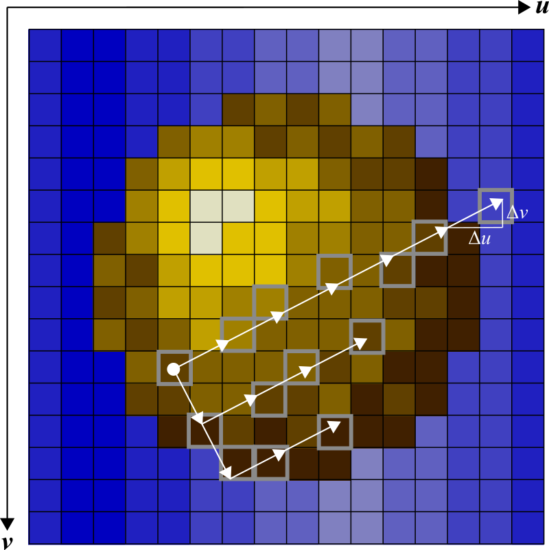
To make the texture repeat, the final values are taken modulo width and height, respectively. Since we want to apply the transformation to a range of pixels on the screen, it is faster to incrementally map instead of doing the transformation from scratch each time. When moving by one pixel to the right (incrementing \(x\)), we move in the following direction through the texture space:
\[\left(\begin{array}{c}\Delta u \\\\ \Delta v\end{array}\right) = \mathbf{M_{\theta,r}}\left(\begin{array}{c}1 \\\\ 0\end{array}\right) = r\left(\begin{array}{c}\cos\theta \\\\ \sin\theta\end{array}\right) \]
Conversely, when moving into the \(y\) direction, the resulting direction in texture space is \(r\left(\begin{array}{c}-\sin\theta \\\\ \cos\theta \end{array}\right)\).
Note that a smaller \(r\) value results in the texture being rendered magnified—we are moving more slowly through the texture space for each step in screen space.

The Implementation
To make the math work on a 6502, some hurdles need to be overcome. Everything needs to fit into 8-bit integer computations, and there is no multiplication instruction the CPU provides outside of bit shifts. Anything more complicated requires larger amounts of machine instructions, which in turn would make everything significantly slower. Since a large amount of the screen needs to be updated for every frame, a lot of computations and a lot of memory access is required to make it work.
To make it a bit easier, I am cutting a few corners. First of all, the effect does not use the full width of the screen. Instead, the rotozoom area is only 192 pixels wide. To the left and to the right are bars that are each 64 pixels wide. Next, the line width offset GFX_OLO/OHI (see my post on the graphics module registers) is set to 256. That has two effects. First, every row of the rotozoomer can now be accessed purely by changing the low byte of the graphics address, GFX_ALO, without having to worry about incrementing GFX_AHI. Second, since every new line only progresses the address by 256 bytes but each line has 320 pixels, the bar on the left and the bar to the right are actually using the same VRAM.
The next corner cut is horizontal resolution. Once a color value has been looked up in the texture, it is drawn twice to screen as two adjacent pixels of the same color. That halves the number of computations that need to be conducted. Similarly, the vertical resolution is halved as well. In the vertical case, this can be done in hardware using the GFX_LRPT register by increasing it from 3 to 7. This is similar to the stretch effect I described in my last post, but the value here is kept constant resulting in a vertical resolution of 90 pixels.

Drawing occurs line-by-line. At every step, I keep track of the current texture coordinates in two variables, u and v. Steps are implemented by adding a du value to a sum value su (in the case of the u direction). If su overflows (V flag set), then the u coordinate is incremented. If there is an underflow (C flag set), the coordinate is decremented. Only the lowest four bits are kept, keeping the coordinate in the range from 0 to 15. The v coordinate is handled equivalently.
The current state of u, v, su, and sv is stored at the beginning of each line. At the end of a line, that state is restored before applying an orthogonal step (see previous section).
Using the u and v coordinates, the texture is accessed. The v coordinate is shifted into the higher 4 bits while the u one is put into the lower ones. The resulting 8-bit value is used as offset to fetch texture data. The du/dv step sizes are precomputed and stored in two tables with 256 entries each. A new value pair is fetched from memory before each frame. After 256 frames, the animation repeats. In the video above, the frame counter is visible over the green LEDs.
The resulting animation renders at about 5 fps on the CPU, which runs at 4.688 MHz. Looking at C64 demos (running on a 1 MHz CPU), I suspect that there is some room for optimization. If you have ideas, hit me up on YouTube or Twitter.
Subscribe via RSS